12 volt trigger out

Hi Uvi,

I tried the Vocomo switch too (see my first message in this thread), both the V1 and V2 version. They don't work as they should and I saw the exact same behaviour you describe. The problem is not the Vocomo switch but an internal issue in the WiiM as described by coppo23 above. There is no ready-made commercial solution for this problem, and it most likely cannot be solved by a software update.

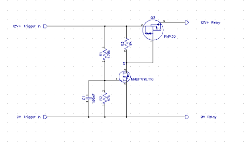
The only solution is to build something yourself or have someone do it for you as per the circuits described above (tested by me and coppo23, working fine), or use an SSR as mentioned in the first message (also tested and working, however see my remarks in my first message). It's not difficult to make for someone with some experience in electronics and soldering.
 
Last edited:
thanks for the information, I still have problems with trigger output from WiiM Pro it’s not working.
Here are the hardware details:

I’m using a switch from Vocomo TSD V1 with trigger input 12 V 33mA ( inner resistance 360 Ohm).

1 Test: Trigger Signal from WiiM Pro is not connected to the switch TSD V1
. The trigger signal from WiiM Pro is connected separately/ manually to TSD V1
after 30sec,the relay from TSD V1 works. Mains is connected to amplifier. Function OK

2 Test: Hardware is the same.
The trigger from WiiM Pro is continuously connected to TSD V1. Start the playback function the Relay will not switch mains to an amplifier. Disconnect and connect the trigger signal from WiiM Pro immediately , the Relay works and switch on the mains. Switch off the playback the Relay will disconnect the amplifier from mains after 2:30.

Please let me know your comments and solutions to solve this severe problem.
The trigger function was one reason for me to buy the WiiM Pro.
As mentioned above, including a 9v or 10v Zener diode (i paired mine with a 30 ohm resistor) between the trigger out and device input should work.

It did the trick for me in any case, although I don’t have an amp with 12v trigger in, I created something similar to @boiing, but using a SSR instead of his relay.
 
Hi I’m a new WiiM user and was also facing issues with the trigger output driving a relay based mains socket with 12V trigger.

I solved it. The WiiM pro trigger output is capable to drive a relay. However not on the rising edge. Therefore I designed a circuit with a very few parts. (See pictures attached).

R1 is 82k
R2 is 33k
C1 is 100uF/16V (defines the delay time (approximately 2s))
Q3 is a logic gate N-FET. I’ve used a IRLZ44N from my own stock but a smaller BS170 would also do the job.

No external powersupply required!
Fully driven by the trigger out of the WiiM.
So the circuit works without additional power source.
 

Attachments

  • IMG_3114.png
    IMG_3114.png
    2.3 MB · Views: 52
  • IMG_3110.jpeg
    IMG_3110.jpeg
    2.4 MB · Views: 35
  • IMG_3111.jpeg
    IMG_3111.jpeg
    2.4 MB · Views: 40
Just like to say how much I love it that we nerd out with home-brewn solutions to something that the manufacturer should have done right in the first place 😅
 
I wonder if the trigger would drive one of these. I have this powering the amplifier that I use with my wiim mini, but it's triggered by an IR controlled relay so that I can control it with my Harmony remote.

Iot Relay - Enclosed High-Power Power Relay

Pretty reasonable price for what you get and I was more comfortable using it than a homebrewed relay running at mains voltage.
 
Hi I’m a new WiiM user and was also facing issues with the trigger output driving a relay based mains socket with 12V trigger.

I solved it. The WiiM pro trigger output is capable to drive a relay. However not on the rising edge. Therefore I designed a circuit with a very few parts. (See pictures attached).

R1 is 82k
R2 is 33k
C1 is 100uF/16V (defines the delay time (approximately 2s))
Q3 is a logic gate N-FET. I’ve used a IRLZ44N from my own stock but a smaller BS170 would also do the job.

No external powersupply required!
Fully driven by the trigger out of the WiiM.
So the circuit works without additional power source.
This is great! I’m not confident enough with mains power safety to attempt some of the other solutions posted but I could try and get these components and have a go at this.

Is there any reason this circuit wouldn’t work in the UK with a 240v supply? I’m guessing it’s irrelevant since I’m still connecting it to an input expecting 12v.
Hi Peter, indeed the 12V trigger doesn't have anything to do with the 240V~ mains.
My suggested circuit is working flawles here with the Vocomo mains switch.
In the meanwhile I designed a small circuitboard which I will put inline with the 12V trigger cable insulated with heat shrink.

I will assembly a few more. In case someone (you?) is interested.

1697836868905.png
1697836910046.png
 
Last edited:
Hi Peter, indeed the 12V trigger doesn't have anything to do with the 240V~ mains.
My suggested circuit is working flawles here with the Vocomo mains switch.
In the meanwhile I designed a small circuitboard which I will put inline with the 12V trigger cable insulated with heat shrink.

I will assembly a few more. In case someone (you?) is interested.

View attachment 2971
View attachment 2972
This looks amazing! I would happily pay the components cost, postage, and something for your labour if you were making up a few of these. Feel free to DM.
 
This looks amazing! I would happily pay the components cost, postage, and something for your labour if you were making up a few of these. Feel free to DM.
Yeah, please continue discussion & negotiations etc by DM - strictly speaking forums like ours don’t permit selling in any form as we can’t get involved in any disputes that might arise out of such transactions, nor I imagine can WiiM be seen to sanction the use of third party mods even if they’re offboard as this is. Cheers
 
C1 is 100uF/16V (defines the delay time (approximately 2s))
Hi Ton, great work! Making this circuit so small with SMD components is a brilliant idea. Quick question out of curiosity: why not use the circuit of 'coppo23' earlier in this thread? Same number of components, but without any delay time ;).
 
Hi Ton, great work! Making this circuit so small with SMD components is a brilliant idea. Quick question out of curiosity: why not use the circuit of 'coppo23' earlier in this thread? Same number of components, but without any delay time ;).
Hi, good question.
For multiple reasons.
1> I wasn't aware of this forum and or this thread at the time I was facing issues.
2> I have a background in electronics and learned myself to determine the real issue.
I've found out that plug out and plug in the 2,5mm jack again while trigger out is active the relay got activated without a problem at the full 12V. But when the tigger became active while the 2,5mm jack was already plugged in nothing happend with the relay (protection). So there was the idea to create a delay.
The circuit you mentioned requires an external power supply which I wanted to avoid.

So the WiiM Pro trigger output is capable of sourcing current for a relay. However not on the rising edge. I'm not fully aware of the internal design of the WiiM Pro but because it's powered from USB I suspect they used a DC/DC converter in order to make the 12V for trigger out.
Without aditional electronics this is typical behavior for low power DC/DC converters.
 
Thanks, I understand your reasoning. I myself also found out the same (using the Vocomo switch): that plugging it in/out did activate the relay but not when leaving it in. I didn't understand why, and I think 'coppo23' did pinpoint the cause earlier in this thread (after I already found a working solution myself).

Just to be clear: both circuits mentioned earlier in this thread do not require an external power supply ;) .

Anyway, have been using both circuits for some time time now and they work without a flaw, and without any delay. I just didn't think of making this into an SMD design and putting it inline in the trigger cable, great idea. Only difference here is that you still need the (rather expensive) Vocomo switch. The earlier circuits in this thread include the 220V relay and might be cheaper if someone is able to solder and make a PCB.

Anyway, thanks for your contribution. I think this thread is a great example of combined knowledge by the community!
Oh sorry. I didn't read / study this thread very carefully regarding the external power supply. (assumption)
There is some kind of thresshold during or just after the rising edge because of the transistor(s) where the trigger output is already stable enough.
So it seems that the the smallest delay is good enough to drive the relay.
 
First question: Is the 12v trigger out AC or DC?

Second: Can you wire in a Solid State Relay, triggered by the WiiM, into a electrical box to turn on an amplifier? Most home amplifiers use ordinary power cords so I can't imagine they draw that much current.

Here is an example:

Thanks
I'd love a 12V trigger.
 
Got a buck converter, adjusted the output to the max (around 11v) , hooked it to a solid state and also a 12v relay, both of them working, hurray

Wiim 12 trigger output to bluck converter then to the relay

Parts used

solid state relay

Buck converter

12V relay module
Hi. Just a bit puzzled and please accept my apologies if I am checking something obvious. Do you really mean Buck convertor?
If you did get this working then I guess the convertor must be delaying the output current until the wiim output has reached a nominal level - in other words - a rather complex way of achieving the same thing as a couple of simple earlier circuits in this thread - mine being one of them!

WARNING; The alarm bell that did ring was if you meant boost convertor. The result may be the trigger output is in overload and only sourcing maybe 3-5v. You are boosting it to 12 to make the relays operate. We already know the design of the Wiim trigger output is 'less than optimal'. Running it in an overload situation like this may or may not damage it. I'd not run the risk if it was me.

Regards
Andy
Hi
It is advertised as a buck converter but the instructions clearly says the output voltage will always be less than the input , so it is not a booster. I adjusted the output volatage to the max it can handle (around 11v) from Wiim trigger out (12V) and it worked fine. I also tried lowering the voltage to 3V for the Solid state relay and it worked without any issues

I do not think it will overload the Wiim circuit as the output is less than 12V. I accept your circuit is simpler but I could'nt bother to assemble it ,so instead bought a £3 off the shelf solution.
 
Last edited:
Hi
It is advertised as a buck converter but the instructions clearly says the output voltage will always be less than the input , so it is not a booster. I adjusted the output volatage to the max it can handle (around 11v) from Wiim trigger out (12V) and it worked fine. I also tried lowering the voltage to 3V for the Solid state relay and it worked without any issues

I do not think it will overload the Wiim circuit as the output is less than 12V. I accept your circuit is simpler but I could'nt bother to assemble it ,so instead bought a £3 off the shelf solution.
Hi. Excellent playing around and a good find! It sounds like it has some sort of soft-start and is simply delaying the power to the relays - as do the other solutions. I didn't want you to risk destroying the wiim if you were using a boost convertor but this probably is a safe ( though slightly jammy) option!
 
Back
Top