Room Correction Mics

I am now confused by the way REW handles calibration files. As I understand it the Dayton Audio calibration files contain gain values to be added to the measured response to obtain corrected values for each frequency. REW subtracts the calibration curve instead of adding it. Maybe I am wrong about the calibration files but allegedly Dayton Audio confirmed it here
 
That should be microphone gain, not gain to be added.

Wouldn't make sense if Dayton Audio did it different from anyone else.
 
That should be microphone gain, not gain to be added.

Wouldn't make sense if Dayton Audio did it different from anyone else.
Can you clarify how the calibration file should be processed? Still confused. It must increase or decrease the measured response.
 
The
Can you clarify how the calibration file should be processed? Still confused. It must increase or decrease the measured response.
The way REW does it is correct.

Ideally the correction values in the calibration file should be 0 dB for all frequencies. Real world microphones can either register a too high or too low SPL. Dayton Audio creates all cal files so that the relative value at 1000 Hz is 0 dB. If the value at any other frequency is positive (e.g. 2.1 dB), then the mic reports a higher SPL then it would at 1000 Hz. If the value is negative (e.g. -2.5 dB), the mic reports a lower SPL then it would have at 1000 Hz.

So, the readings are not gain that should be applied to the measurement. They are just relative values of "too much" or "too little".

At least for the iMM-6C (I didn't check this with any of the other variants) the first line seems to provide some absolute gain value like e.g. -36.6 dB. This could be the absolute gain of the microphone. My UMIK-12 e.g. reports a gain of -12 dBFS to REW. However, this value is not taken from the MiniDSP calibration file, but directly from the device properties. Lines starting with an asterisk are ignored by REW so it remains unclear to me what this first line is actually for.

Edit:
Slight correction: The UMIK-1 "reports" itself as "12 dB" (whatever that means here) and it apparently only does so in the device name.
 
Last edited:
The

The way REW does it is correct.

Ideally the correction values in the calibration file should be 0 dB for all frequencies. Real world microphones can either register a too high or too low SPL. Dayton Audio creates all cal files so that the relative value at 1000 Hz is 0 dB. If the value at any other frequency is positive (e.g. 2.1 dB), then the mic reports a higher SPL then it would at 1000 Hz. If the value is negative (e.g. -2.5 dB), the mic reports a lower SPL then it would have at 1000 Hz.

So, the readings are not gain that should be applied to the measurement. They are just relative values of "too much" or "too little".

At least for the iMM-6C (I didn't check this with any of the other variants) the first line seems to provide some absolute gain value like e.g. -36.6 dB. This could be the absolute gain of the microphone. My UMIK-12 e.g. reports a gain of -12 dBFS to REW. However, this value is not taken from the MiniDSP calibration file, but directly from the device properties. Lines starting with an asteriks are ignored by REW so it remains unclear to me what this first line is actually for.
I am sure you are right but is the opposite of what tech support from Dayton Audio said in my link above. It wouldn't be the first time tech support has been wrong 🤣
For my case I calculated the calibration curve by calculating TRRS curve/USB curve instead of USB curve/TRRS curve so my calibration file was reversed. Once I corrected that the results didn't look too bad.
 
I had always thought this was the right thing to do.🤔😅

"The calibration files are essentially a filter curve to an extent to align the microphone to a zero point."
 
Don't make me think about it again ... :ROFLMAO: ... cause I might be wrong in the end ...

No, of course not. ;)

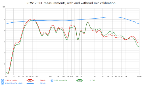
Strictly speaking I cannot proof that REW does it right, but only that it works the way I described it. Here are two random SPL measurements, taken with a UMIK-2. The whole setup wasn't moved during the measurements. It's just that one is with the calibration file loaded while the other is not. For comparison, I also imported the calibration file itself and added 65 dB to make it show close to the measurements.

SPL w and wo cal.png

It's easy to see that REW does indeed subtract the values in the calibration file from the result. But we kind of knew that before, didn't we? In itself it doesn't proof anything.

But given the ages old cooperation between REW and MiniDSP I simply cannot imagine that John Mulcahy would have implemented this the wrong way around.

Calibration files tend to fall off (into the negative range) at the frequency extremes. This is exactly what you would expect from the transfer function of a transducer (even if our mics are not dynamic microphones but condenser microphones). It makes no sense that a mic would start to produce more output at the extremes of the frequency range. It makes a lot more sense to think that some (dampened) resonance of the capsule (or the capsule in its enclosure) would create a higher output at some frequency in the middle of the range. And that's what I see here.

Edit:
This part ...
"-40 dBV, re. 0 dB = 1V/Pa), thus the reference level would be -40dBV."
... makes a lot of sense, nonetheless (but doesn't really help REW).
 
Last edited:
Also, the REW documentation is pretty clear on this topic:
The calibration file is a plain text file which by default has the extension .cal, though other extensions are also accepted. It should contain the actual gain (and optionally phase) response of the meter or microphone at the frequencies given, these will then be subtracted from subsequent measurements.


This leaves us with two possible scenarios:
  1. Dayton Audio's calibration files are unsuitable for use with REW (and also HomeCurve).
  2. Dayton Audio's support is not suitable for supporting customers.
Given the fact that the DA microphones.sgow the same basic behaviour as the MiniDSP mics, I'll pick option 2.
 
Don't make me think about it again ... :ROFLMAO: ... cause I might be wrong in the end ...

No, of course not. ;)

Strictly speaking I cannot proof that REW does it right, but only that it works the way I described it. Here are two random SPL measurements, taken with a UMIK-2. The whole setup wasn't moved during the measurements. It's just that one is with the calibration file loaded while the other is not. For comparison, I also imported the calibration file itself and added 65 dB to make it show close to the measurements.

View attachment 13171

It's easy to see that REW does indeed subtract the values in the calibration file from the result. But we kind of knew that before, didn't we? In itself it doesn't proof anything.

But given the ages old cooperation between REW and MiniDSP I simply cannot imagine that John Mulcahy would have implemented this the wrong way around.

Calibration files tend to fall off (into the negative range) at the frequency extremes. This is exactly what you would expect from the transfer function of a transducer (even if our mics are not dynamic microphones but condenser microphones). It makes no sense that a mic would start to produce more output at the extremes of the frequency range. It makes a lot more sense to think that some (dampened) resonance of the capsule (or the capsule in its enclosure) would create a higher output at some frequency in the middle of the range. And that's what I see here.

Edit:
This part ...
"-40 dBV, re. 0 dB = 1V/Pa), thus the reference level would be -40dBV."
... makes a lot of sense, nonetheless.

Yes, I was comparing the data I have posted in the past.
As a result, I have determined that you are correct.

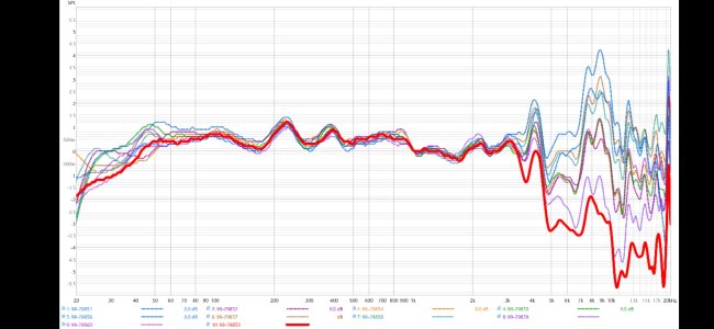
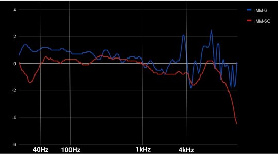
Here is my IMM-6C calibration file. The red line shows roughly -1dB at 1kHz~4kHz.

And this is the result of my actual microphone recording of the speaker output before and after calibration. It does not exactly reflect the values in the calibration file, but I can see that the post-calibration measurement shows a partial +1dB addition at 1kHz~4kHz.

I have not manually corrected the PEQ values using the calibration file values, but this thread has been very informative.

Thanks.😄
 
Also, the REW documentation is pretty clear on this topic:


This leaves us with two possible scenarios:
  1. Dayton Audio's calibration files are unsuitable for use with REW (and also HomeCurve).
  2. Dayton Audio's support is not suitable for supporting customers.
Given the fact that the DA microphones.sgow the same basic behaviour as the MiniDSP mics, I'll pick option 2.
I have asked Dayton Audio the question again. Let us see what they come back with this time 🤣
 
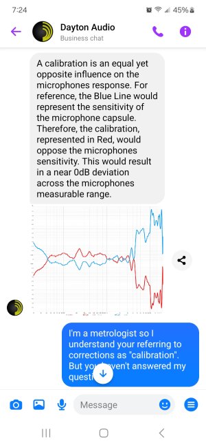
And this is how Dayton technical service described the effect of their calibration file on Oct 6:

Screenshot_20241022_192459_Messenger.jpg
 
Again Dayton Audio are saying the calibration values are added to the microphone response and not subtracted. Does that mean their calibration files need to be inverted to use them with REW?
Ask Dayton Audio this question directly.

If what they say about their cal files was true, then yes, the file would need to be inverted for REW to make proper use of it. However, it is simply not credible that the mic's sensitivity would increase towards the extremes of its frequency range.

PS:
I did search the Official REW (Room EQ Wizard) Support Forum over at avnirvana.com. I didn't mention to find any information specific to Dayton Audio calibration files.
 
... However, it is simply not credible that the mic's sensitivity would increase towards the extremes of its frequency range...
This really isn't about the mic sensitivity per se.
Rather it's about the correction table and how it's implemented in software.

Why would REW apply this data, from 2 major mfrs, in the wrong polarity?

Edited out my comment about mic actual responses. I can only infer the response from the calibration file since I haven't the means to verify it.
 
Last edited:
Which is it in the end? 😂

Essentially, the calibration file should be the data to correct the problem. In that sense, Dayton's assertion appears to be correct.

My IMM-6C and IMM-6 seem to show different trends in the low frequencies, but I don't see why individual microphones would show different trends in the high and low frequencies.

1000001283.jpg

Definitely I am confused.😂
 
The response I got from DA (posted above) would indicate the "calibration file" is a table of corrections, so they are numbers of opposite polarity to the raw response (mirror image).
My file for my Umik-1 is similar, with numbers that go negative at the extremes... which suggests there's a sharp rise at each end.
This IS possible. The capsule inductance & resonances might be tailored to be relatively flat thru the middle, with sacrifices at the extremes.

These aren't expensive mics.
I am an idiot, so I will ask again.

The calibration file has nothing to do with microphone sensitivity. The fact that my IMM-6C shows -4dB at 20kHz does not indicate that the microphone is less sensitive, it simply indicates that it needs to be calibrated +4dB at 20kHz.

Therefore, it is not surprising that the values of individual microphones differ significantly in the low and high frequencies.

Is this a correct interpretation?

(However, this is the opposite conclusion from the results I compared on AudioTool, and I may need to do another precise test...)
 
Ask Dayton Audio this question directly.

If what they say about their cal files was true, then yes, the file would need to be inverted for REW to make proper use of it. However, it is simply not credible that the mic's sensitivity would increase towards the extremes of its frequency range.

PS:
I did search the Official REW (Room EQ Wizard) Support Forum over at avnirvana.com. I didn't mention to find any information specific to Dayton Audio calibration files.
I have asked them but no reply yet. Now we have seen two responses from them which appear to be wrong. I might ask on the AudioTool forum as well as the iMM6 is a common mic for that app.
 
Why would REW apply this data, from 2 major mfrs, in the wrong polarity?
I trust it doesn't.

The response I got from DA (posted above) would indicate the "calibration file" is a table of corrections, so they are numbers of opposite polarity to the raw response (mirror image).
And this is exactly not how REW does it.

My file for my Umik-1 is similar, with numbers that go negative at the extremes... which suggests there's a sharp rise at each end.
Yes, the tendencies are very similar. But the only indication I can get from that is that Dayton Audio must be wrong, if MiniDSP and REW are right.

This IS possible. The capsule inductance & resonances might be tailored to be relatively flat thru the middle, with sacrifices at the extremes.
Yes, but the effects at the extremes will be in the opposite direction. There is absolutely no reason to think that the output would be higher at the highest and the lowest frequencies. Once again, these are not dynamic microphones but condenser microphones. There's no coil and no magnet, forget about any meaningful inductance.

This really isn't about the mic sensitivity per se.
Rather it's about the correction table and how it's implemented in software.
One follows strictly from the other, doesn't it? The act of calibration (independently of which conventions might exist for the file containing the data) is intended to counteract irregularities in the mic's sensitivity.

If people start inverting the the sign of data lines DA's cal files before using them with REW, the result could be catastrophically wrong ...
 
Back
Top